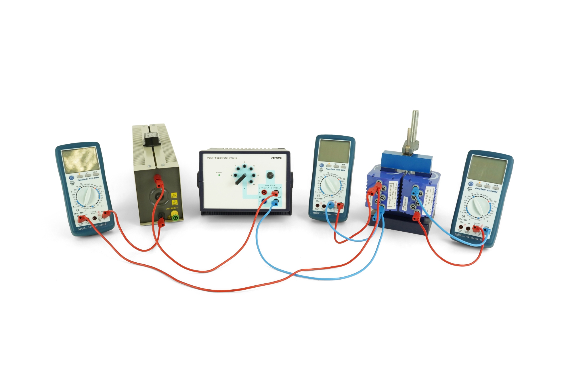
Transformer
Article No: P2440101
An alternating voltage is applied to one of two coils (primary coil) which are located on a common iron core. The voltage induced in the second coil (secondary coil) and the current flowing in it are investigated as functions of the number of turns in the coils and of the current flowing in the primary coil. Benefits Coils with several tappings for various combinations of winding numbers between primary and secondary coil Quick, easy, and neat set-up Tasks The secondary voltage on the open circuited transformer is determined as a function of the number of turns in the primary coil, of the number of turns in the secondary coil, of the primary voltage. The short-circuit current on the secondary side is determined as a function of the number of turns in the primary coil, of the number of turns in the secondary coil, of the primary current. With the transformer loaded, the primary current is determined as a function of the secondary current, of the number of turns in the secondary coil, of the number of turns in the primary coil. Learning objectives Induction Magnetic flux Loaded transformer Unloaded transformer Coil